







Specify the number on a 2D section through the prong axis — Section A-A, cut through the stone center and one prong — not on the 3D mesh, and dimension the metal between the seat bearing surface and the outer face of the prong. For a 6.5 mm round moissanite in S925, put 0.95 mm minimum on the CAD, pre-polish, and 0.80 mm minimum on the finished, set and polished prong, with a one-sided tolerance of +0.05/−0.00 mm. The PO should then require the factory to confirm both figures in writing before it quotes, and to prove them by sectioning one first-article casting at the seat. Below 0.80 mm finished, refuse the design: that is where a silver prong stops being a setting and becomes a wear item.
What Prong Dimension Actually Holds a 6.5 mm Stone?
A prong holds a stone with the metal behind the seat, not with its outside diameter. A 1.00 mm prong sounds solid until the setter cuts a 0.30 mm bearing seat into its inner face. The wall left behind is 0.70 mm in the CAD file and about 0.55 mm after filing and polishing. The drawing still says 1.00 mm, and the ring still fails.
Scale makes it worse. A 6.5 mm round has roughly eighty times the volume of 1.5 mm melee, and its girdle presses on four small bearing surfaces. Every knock on the crown becomes a prying load at the seat — which is also where polishing removes the most metal.
Silver is the wrong metal to be stingy with. Sterling is 92.5% silver; in the United States, an item may be described as silver or sterling silver only if it is at least 925/1,000 fine, as the FTC’s consumer guidance on precious-metal jewelry states. The 7.5% copper adds hardness, but cast sterling still creeps under steady load and wears against a hard girdle. Thickness is the only lever that costs nothing in alloy.
Why the 0.5 mm and 1.0–1.2 mm Figures Do Not Answer This
The 0.5 mm figure is not a seat-wall specification. At its source it is a tip-base rule: for the same 6.5 mm round, the prong-bend guidance asks for “a wall at the base of the tip no thinner than about 0.5 mm” — the metal above the girdle that a re-tip has to rebuild. The figure is also the one usually quoted for micro-pavé claws on 1.0–1.5 mm melee, where the stone weighs a fraction of a point. Those are different measuring points: the tip base sits above the girdle, the seat wall sits between the bearing surface and the outer face of the prong, and a 6.5 mm stone can pass a 0.5 mm tip-base check with 0.55 mm left at the seat. The 1.0–1.2 mm figure is usually a prong diameter, quoted without reference to seat cut, stone size or alloy. A factory can meet it and still deliver a 0.55 mm wall at the seat. Neither number tells a CAD operator what to dimension, or a buyer what to reject.
Where Exactly Should the Prong Thickness Appear in the CAD?
A 2D Section, Not the 3D Mesh
STEP and STL files carry geometry, not tolerances. A factory quotes from the mesh — stone count, weight, metal price — and nothing in that file states a minimum wall. Worse, a general ±0.05 mm tolerance applied to a 0.95 mm wall lets it read 0.90 mm with no deviation flagged. The number has to live on a drawing sheet issued with the model, repeated in the quote, and attached to the PO.
Section A-A Through the Stone Center and One Prong Axis
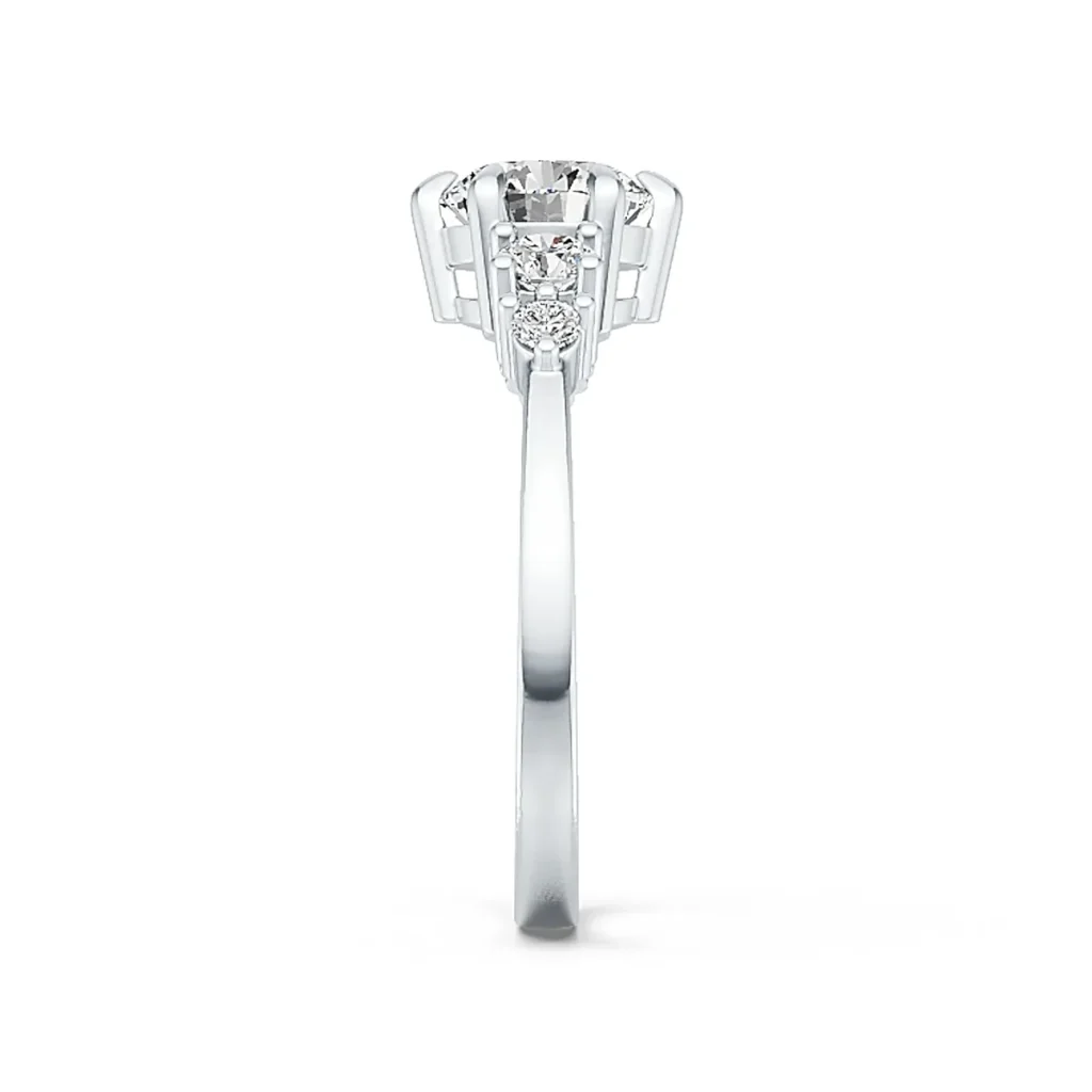
Cut a plane through the stone center and one prong axis, and section the assembly with the stone as reference geometry. This is the only view where the seat cut, the bearing ledge and the wall behind them appear in true profile. Dimension the shortest distance from the bearing surface to the outer prong face, the radial seat depth, the ledge width, the prong diameter at the girdle plane, and the tip diameter with the height available for a re-tip. Add Section B-B at girdle height and a 5:1 detail; the isometric render is for approval only.
The Dimensions the Drawing Sheet Needs
| Dimension | CAD, pre-polish | Finished minimum | How it is checked |
|---|---|---|---|
| Seat wall: bearing surface to outer prong face | 0.95 mm MIN | 0.80 mm | Sectioned finished piece, 10× |
| Seat cut, radial depth | 0.25 mm MAX | 0.25 mm | Section A-A against the stone |
| Bearing ledge width | 0.25 mm | 0.20 mm | Section A-A, 10× loupe |
| Prong diameter at girdle plane (Section B-B) | 1.20 mm MIN | 1.05 mm | Caliper plus section |
| Tip diameter above girdle | 0.95 mm | 0.80 mm | Caliper |
| Prong height above girdle for re-tip | 0.60 mm | 0.45 mm | Section A-A |
| Voids on the sectioned face | None at 10× | None at 10× | Visual, 10× |
Every finished value is the CAD value minus the 0.15 mm finish allowance, with two exceptions: the seat cut holds at 0.25 mm MAX, because a deeper cut only eats the wall, and the bearing ledge loses 0.05 mm, from 0.25 to 0.20 mm, not 0.15. A polishing route that removes more does not get to eat into the 0.80 mm floor.

Dimension as a Minimum, With a One-Sided Tolerance
Write 0.95 MIN, not 0.95, and add a title-block note: “PRONG SEAT WALL MINIMUM, PRE-POLISH; FINISH ALLOWANCE 0.15 mm ON EXPOSED PRONG SURFACES; TOLERANCE +0.05/−0.00.” State the finished value separately — “FINISHED MIN 0.80 AT SEAT” — because a polisher cannot infer the allowance on a curved, hand-worked surface. Two numbers, two stages, one section.
Model the stone from the parcel you will actually set. A 6.5 mm moissanite is not the same body as the CAD library’s generic diamond: girdle thickness, crown angle and pavilion depth differ, and the seat is cut to the girdle. A wrong reference stone makes the setter deepen the seat, and the wall goes with it. One formula keeps this honest: minimum prong diameter = 0.95 mm + seat cut depth. At a 0.25 mm seat, that is 1.20 mm.
Why Is 0.80 mm the Floor, and What Should a Buyer Refuse?
No published standard fixes a prong wall for a 6.5 mm stone in silver. The 0.80 mm figure is a purchasing floor sized for finishing, wear and one re-tip — not a claim that thinner prongs always fail tomorrow.
The Stiffness Math
Treat the wall behind the seat as a short beam of constant width: bending stiffness rises with the cube of its thickness, and bending stress at the same load falls with the square. A 0.80 mm wall is not 33% stiffer than 0.60 mm; it is 2.4 times stiffer (0.80/0.60)³, and bending stress at the same load is about 44% lower, 1 − (0.60/0.80)². At 0.55 mm — what you get from a 1.00 mm prong with a 0.30 mm seat and normal polishing — the section keeps about a third of its stiffness (0.33), and stress more than doubles (2.1×). That is the difference between a prong that springs back and one that stays bent.
The Re-Tip and Porosity Allowance
Budget 0.10–0.15 mm per re-tip and re-polish. Starting at 0.80 mm, one re-tip leaves 0.65–0.70 mm and a second leaves 0.50–0.60 mm — rebuild territory, not shave-again territory. Starting at 0.55 mm, there is no first re-tip. Porosity compounds it: a 0.80 mm wall with a third of its section in voids behaves like 0.53 mm, and the seat is where feed metal arrives last in a thin prong. So the wall dimension is only half the specification; the other half is a sectioned face with no voids visible at 10×.
The Refusal List
Refuse the quote or the design when:
- the finished seat wall is below 0.80 mm, or unstated;
- the CAD wall is below 0.95 mm, or there is no finish allowance;
- the prong is below 1.20 mm at the girdle plane with a 0.25 mm seat;
- the answer is a nominal size (“we use 1.0 mm prongs”) instead of a seat dimension;
- general tolerance is allowed to apply to the wall;
- the seat is cut to the pavilion instead of the girdle, so the stone rocks on a cone.
Thin prongs also fail in ways blamed on the plating bath; see bent prongs after the polishing machine.
A Size Schedule for Other Stones
Scale the same logic: 4.0–5.0 mm stones, 0.60 mm finished wall; 5.5–7.0 mm, 0.80 mm; 7.5–9.0 mm, 1.00 mm; 9.5–11.0 mm, 1.20 mm. Raise the CAD value by the allowance and add the seat cut to get the prong diameter. Six prongs add redundancy, not a lower floor: each seat still wears at the same rate.
What PO Language Makes the Thickness Enforceable?
A drawing the order does not reference is a suggestion. Name the file and revision, repeat both values, and make written confirmation a condition of the quote rather than a promise made at sampling.
Prong wall — 6.5 mm moissanite styles, all SKUs on this PO. Seller confirms in writing, in the quotation and before order acceptance, that (a) drawing [file], revision [x], carries a 0.95 mm minimum pre-polish seat wall on Section A-A through each prong axis; (b) the finished, set and polished wall from seat surface to outer prong face is not less than 0.80 mm on every prong; (c) tolerance on both is +0.05/−0.00 mm, outside general drawing tolerance; (d) Seller will section one first-article casting per SKU and supply a measured report with a 10× photo before bulk release; (e) any proposal below these values is non-conforming and needs Buyer’s written approval before casting. AQL 2.5 final inspection does not satisfy this clause.
Ask for a Confirmation Drawing, Not a Sentence
The cleanest RFQ reply is a marked-up copy of your Section A-A with the seat wall circled, the finished value beside it and the stone reference identified. “Prongs are 1.0 mm, standard quality” cannot be measured, compared between suppliers or enforced after the deposit. A factory that will not return the drawing has told you how it will handle a claim.
Why AQL 2.5 Will Not Catch This
Final inspection is visual and dimensional from the outside: it finds bent prongs and plating blisters, not the wall behind a set stone. Like pre-plating and post-plating checks, the internal dimension needs its own destructive gate, because a post-plating AQL check cannot verify internal porosity or wall thickness. Name the section report as a separate deliverable with a remedy: remake at the seller’s cost if any sampled prong measures below 0.80 mm.
How Do You Measure the Seat Wall After Polishing?
Section a finished piece. Cut through the prong axis on the same plane as Section A-A, mount and polish the cut face, and measure at 10× with a toolmaker’s microscope or image analysis; keep the photo with the approval file. Measure the finished, set, polished ring — not the wax, not the raw casting, not before the seat is cut.
Two pieces per SKU catches a systematic miss and is cheap to repeat on reorders. Treat one as the destructive test and seal the other as the retention standard, the same logic behind sample room vs production run.
Frequently Asked Questions
Is a 1.0 mm prong thick enough for a 6.5 mm moissanite in S925?
Only with a shallow seat. A 1.0 mm prong and a 0.30 mm bearing cut leave 0.70 mm before polishing and about 0.55 mm after — under the floor. Holding 0.95 mm of CAD wall with a 0.30 mm seat needs a 1.25 mm prong at the girdle plane. Diameter alone never answers it.
Should I specify prong diameter or wall thickness?
Both. The seat wall is the strength specification; the prong diameter is the manufacturing input that produces it. Put the wall on Section A-A as a minimum and the girdle-plane diameter on Section B-B.
Can a factory hit 0.80 mm at the seat on a 4-prong basket?
Yes, with prong stock near 1.20 mm at the girdle plane and a seat no deeper than 0.25 mm. If a supplier says it is impossible, the limit is usually its CAD library, finishing route or a prong size chosen for metal cost.
Does plating add strength to a silver prong?
No. Rhodium and anti-tarnish layers are fractions of a micron thick and follow the surface. Never count them toward the minimum, and never let a plated sample hide a wall that was thin before the bath.
Do six prongs let me go below 0.80 mm?
No. Six prongs add redundancy, but each seat carries the same local wear and prying load and is cut the same way. What changes is how much one failed prong costs you.
What This Means for an OEM/ODM Order
At Amara Jeweiry, OEM/ODM runs on a CAD confirmed before printing, a wax model you approve before any metal is cut, and samples that ship 7–10 days after CAD sign-off; full OEM/ODM starts at 50–100 pieces. Setting is in-house with ±0.05 mm stone position tolerance under the microscope, a 100% claw check and pull test, and AQL 2.5 final inspection. None of it replaces a seat-wall dimension: neither the pull test nor the AQL check sees the wall behind a set stone. Send the Section A-A with the 0.95/0.80 callouts and ask for the confirmation drawing back — the OEM/ODM process starts from your drawing, not a stock prong size.